Wednesday 8 May 2013

The Galley

So how much could I get into an 8ft x 6ft gap?
How would I maintain the access panels for the hydraulics that ran through it?
These were the first questions I asked myself, as I stared at a blank piece of paper. I had got hold of an ex display solid oak kitchen, and although there were far more units than I needed I was struggling to put any sort of design together.After a while I managed to formulate an idea, free standing units into a U shape and using wall units as base units, with a little modification I had a galley.


To overcome the access panel I constructed a false floor, for the units to sit on, at plinth height. For normal inspection I would be able to remove the plinth, lift the access panel, and by means of work lamp, inspect the hydraulics. For more serious works with a little effort I would be able to remove individual units.
I decided to leave the worktops at 600mm, so that we could choose from full size hobs and sinks. Also as we intended to live aboard it would be more practical.
However the 600mm tops wouldn't work against the bulkheads and leave space to move in between.


Again a little modification sorted the problem.
I used an 800mm wall unit to make a corner unit trimmed down to a depth of 240mm, but still used a 400mm worktop this created a mini breakfast bar effect. On top of this I trimmed a decorative glass door wall unit to the shape of the roof. The opposite bulkheadwas just a case of trimmingthe service wings off of a standard 400mm base unit and fitting a 540mm top
On the port wall I planned a straight 500mm deep x 900mm long top to cover the fridge. I used a wine rack to make up the 300mm difference.
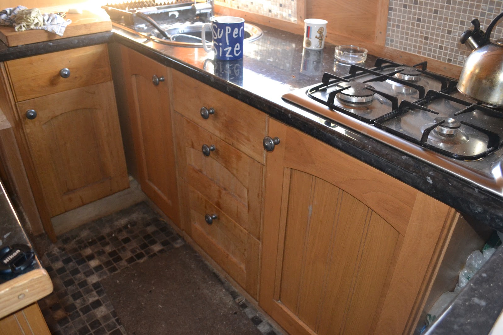
We chose black worktops and stainless steel sink and hob. I used some stainless steel tiles as splash backs and framed these in solid American White Oak.
I also trimmed all the open edges of worktop with the oak.
A small unit was built between the corridor entry and the fridge unit that was only 150mm deep but filled an otherwise wasted void.
Over a period of time some minor changes have taken place for practical and aesthetic reasons and now we are really happy with it, even though we still have to install an oven.

Calorifier

I had already decided that a horizontal calorifier would fit in best with my design
The ideal position for the calorifier was under the bed, this would later prove to keep our feet warm on cold winters nights.
Using the frame I had made for the bed I housed the calorifier in one of the storage spaces I had created.


I left a modicum of space to allow connection of the pipework.
I bolted the unit down to the floor with the feet provided.
The pipe work was relatively simple, all the spigots were clearly marked and accepted the pushfit system I was using. I teed the cold supply into the calorifier and let the pipe run through to the back cabin for possible installation of a washing machine at a later date, so I capped the pipe with a washing machine valve.
I connected the hot to a shut off valve then through an expansion tank to the shower room and on to the galley, leaving tee positions where required.
I then fed some pipes into the back cabin for later connection to the engine and heating unit. I also fed the overflow into the bilge.
I connected the immersion to a fused spur on my 240v ring to provide hot water.


I capped all open pipes and turned on the pump, after a while of listening to the sound of running water, albeit in a sealed system, I thought better check the joints! I found two minor weeps, the first was on the cold expansion tank joint, quarter turn with a spanner cured that one. The second was a bit more time consuming as I found I had crushed an insert somehow and had to replace a small section of pipe work. I also installed a drain off valve near the calorifier as I'd been caught out with the leak.
For several months we had been using water from camping containers, carried daily from the nearest tap on the mooring section, and now we had water on the boat. It had taken three long hosepipes to fill the tank with 650 Litres of water and I realised I couldn't fill a kettle from it yet!
Now I needed to fit a tap either in the galley or shower room, I chose to fit the galley........

Water Tank and Pump

Next job was to get fresh water on the boat, I was spending an enormous amount of time camping on her now. Under the well deck was the ideal location and very common on narrowboats. The slight problem that I had was the bow thrusters, although the access panel was in the well deck it protruded into the void below, this was also the entry point for the electric and hydraulic power supplies for them. After long searches on the internet, with no luck it was decided that we would need to go bespoke and have one manufactured.
I drew the shape to follow the curve of the swim until it was a few inches short of the bow thruster housing, then straightend the line for ease of manufacturing.
I then squared back to the main cabin about 3/4 of the width of the boat, in order to leave an access crawl way to the bow thruster housing. After measuring and drawing I realised that really it was a simple rectangle with a corner cut off. I worked the height out to slide under the well deck but still be as big as possible, marked the positions of the inlet, outlet and air vent and my drawing was completed. Now who to send it to for a quotation to manufacture in stainless steel.
By complete chance Simon Waine from the boat yard passed while walking his dog, he saw the drawing added a few helpful comments and alterations and stated he could sort it out. I gave him the drawing and said let me know price and delivery which he duly did.
Three weeks later I had this monstrous stainless steel cube on my boat. For some unknown reason I cannot find a photo prior to installation.


The tank was fitted under the well deck quite easily, I had to cut a hole in the forward port locker floor to access the inlet connection, but I figured I could turn this into an access panel at a later date.
I fitted some treated 3*2 around the footprint to lock the tank into position, a false wall would be constructed at a later date, that could be lined to match the interior. My first fix plumbing was then connected through a shutoff valve, expansion chamber, filter, pump, second shutoff valve, second filter then to the tank itself. This gave me the option to service any part of the system without the need to drain the tank, which I worked out would hold 650 litres of fresh water. I later added some drain off valves anyway as a precaution. The electrical supply was to be 12v for the pump and I hadn't started this yet so I just ran two colour coded cables back to my fuse box location, along the skirting trunking on the port side, where I had an old car battery for test purposes.

Layout and Design

I had made a scale drawing of the boat and cut some cardboard templates of the ideal sizes of the bedroom, galley, shower room and dinette.
After moving them around to suit windows, then trimming to suit the basic layout was in place.
Everything was really governed by the swan hatch on the starboard side, the port side has two but their location did not influence the interior.
Using 18mm blockboard that was veneered on both sides I made two half height bulkheads. I scribed these to the side of the boat and placed them 3ft from the centre line of the hatch.


These would become the back rests of the dinette. The dinette would also convert to a double bunk


With these in place I then marked out the floor for the galley, shower room and bedroom. Using some 2*2 uprights I created a temporary frame of my layout, with a few minor alterations I was happy with the layout. I then installed three full height bulkheads on the boat, these framed the permanent double bunk and the shower room. From the shower room bulkhead to the first half height bulkhead was a litter over 8ft, this would become the galley.


 So from the bow doors I had 14ft lounge, 6ft dinette, 8ft galley, 5ft6" shower room, 6ft4" bedroom and a back cabin of 5ft8". Again on the starboard side I planned a fireplace for the stove, approximately central on the lounge wall.


 I then set to work building the required elements. Some will be more detailed in future blogs.

Monday 6 May 2013

Lining

We had chosen to use American White Oak for our interior so we ordered a quantity of real veneer panels, 12mm for the sides and 6mm for the roof.
Firstly I worked out that I could get three sections below the gunwales, if I had the grain running vertically, out of one sheet. After cutting I varnished the backs to act as balancing (prevent boards from twisting and curving ) and drilled along the edges with a plug cutter so the screws would disappear later on. All the edges were sanded and varnished.


Cut outs were made where the sockets would be required, then the boards were screwed to the battens. I did not use any adhesive at this point because I want these panels to be removable at all times.
Above the gunwales I chose to run the grain horizontal along the boat


. This would give me a contrast of light and dark shadows to break up any monotony.
Of course this would make fitting a lot more difficult as the boat sides were leaning in towards me. Also this is a solo project so lining up the panel and fixing required more than 2 hands. However with the use of a "workmate" and some legs I clamped into it I figured out a system that worked.
Although the boards were cut to length and height, I ignored the window and porthole positions, as I prefered to do that in position using a jigsaw and small hand router.


For the roof I used 6mm boards so they would follow the curve nicely. I had run the battens down the length of the boat, as opposed to across the width, this formed a slight saddle back look to the roof.
Again I cut the holes for the mushroom vents after the boards were attached to the battens.
Where the roof and sides met I was going to create lighting pelmets to keep the headroom in the main area of lounge, dinette and galley.
After fitting the boards were varnished on the fronts.

Plumbing and Electric First Fix

Having decided on our layout on paper I was able to run the water pipes from the tank position to the calorifier along the starboard side of the boat. I installed tee joints for galley and shower room locations. Using red and blue talon clips to identify hot from cold I installed a plumbfast system of flexible piping, along the skirting channel. The cold ran from the bow to the calorifier position and then the hot from calorifier to sink position in the galley area. Again I left tee joints for 2nd fix. On the port side I planned to install a couple.of radiators so I replicated the pipework for flow and return.


I used the natural trunking under the gunwales to run the cabling for the 240v shoreline. A very basic ring circuit for sockets only. So starting from the consumer unit position I ran 2.5mm LSOH flex cable around the boat and clipped it under the gunwales, I used nail on clips but replaced the nails with screws, which was easier as I laid on my back to attach them. Leaving loops where required I returned the cable to the consumer box location to form the ring.


Friday 3 May 2013

Insulation Part 2

So the battens were attached with self tapping screws and I coated the back with silicone as it came into contact with the steel


The battens were squared from the floor, as I had used string lines to install it.
I then fitted the 1" polystyrene between the battens, fixing and sealing with silicone.

This resulted in a thickness of 3" below the gunwales and 2" above. Under the gunwales were insulated with strips of polystyrene, again fixed with silicone.


Some areas of the boat were difficult so
I used spray foam from cans to ensure a good seal.
The sides were made longer to create a natural trunking for cables. Where the cable runs were to feed sockets I used 9mm ply channels, so there was no contact between cable and polystyrene, as this could cause corrosion to the outer sheath of the cable.


Skirting channels were also created with ply to house the plumbing.

Insulation Part One

There  were three types of insulation that we considered
1 Sprayfoam. This was our favorite option and we were disappointed to have to rule it out. The few people that were prepared to haul their equipment down the towpath also needed electric, lighting and that the shell was dried out. The major problem was we were using my work generator and had no meams of going under a cover or anything. We investigated every avenue open to us but to no avail.
2 Fibreglass This was quickly ruled out mainly due to fire resistance and it's actual insulation properties.
3 Polystyrene So this is what we were left with, I sourced a company in Birminghamthat could supply 8*4 sheets of fire resistant polystyrene in various thicknesses as long as I bought pack quantities and collected.

With this now on the boat I set about the installation, using the structure of struts throughout the boat I cut panels of polystyrene, dried the area from condensation, and covering the backs with silicone, forced the polystyrene between each angle iron strut.


Using 2" thickness below the gunnels and 1" on the ffood and sides above she soon looked different.
Then I fixed treated 2*1 roof battens to the struts at 600mm centers to the struts
Then I repeated the process with1" polystyrene between my battens,again sealing with silicone.
The roof was completed in a similar manner using 3/4" materials.


Tuesday 30 April 2013

Fitting the floor

As Purrrfect she had bow thrusters fitted and the hydraulics ran the length of the boat, this dictated that I would have to raise the floor.
After cutting lengths of 3*2 to size I fixed them to the base struts using 3" stainless steel self tapping screw.
Then I fixed further lengths of 3*2 at 90 degrees to run the length of the boat and clear the hydraulic pipes.
These were also strategically placed to create access panels to the ballast and the hydraulics.
Using 18mm spruce ply, that I had treated on both sides prior to cutting, I created a series of access panels 300mm wide to run the complete length of the boat covering the hydraulics. This gave me a straight line that I used as a datum point for all setting out.
For the rest of the floor I cut panels at 27" centres to align with the ballast and then trimmed them to the width of the boat.
All of the edges were sanded and then treated with yacht varnish.
As the panels were fitted the substructure was adapted to become removable at the access panel positions
Soon the floor was completed and the difference was amazing. I could set up work benches, a mini kitchen from our camping gear and even a chair and small table.

Sunday 28 April 2013

The Story Continues

So we had found the ideal size and style for our boat,we were also offered a mooring by Brinklow Boat Services, where we could work on her whilst she was still in the water.The hull had been blacked and the anodes renewed, she had also had a coat of primer to protect the new steel where the front bulkhead had been moved and of course the areas that had been repaired. The survey report was good and so the new shaped shell was born.
The first thing we had to do was clear some remnants of floor, burnt insulation and debris from the recent works.
We went about this task with vigour, working from the stern to the bow in a very efficient manner.
As we cleared each section I lifted the ballast, 2*2 paving slabs and waxoiled the base plate. Fox and I filled umpteenbags with debris and after a week of evenings we were ready to start work proper.

Frustration

The trouble with blogging from the mobile phone is that you cannot see what your writing as the keyboard hides the script. Please bear with me I have 3 years to catch up but I promise to be brief. Now I am going to learn how to upload photos.....Hopefully

Finding Purrrfect

On the 22ndof May 2010 my wife "Foz" and I Chris purchased a narrowboat shell called Purrrfect The boat had been in a horrendous fire but the hull, engine and most of the steel had survived.
Originally she was a semi-traditional style boat but with the required alterations to correct the damaged steel she became a cruiserstyle. The engine is a beta marine 42 with only 324 hours on the clock and in perfect working order.